
To program the ESP-8266 through the Arduino IDE, we need an additional board driver.
First run the Arduino IDE and go to File –> Preferences and in the Additional Boards Manager URLs Section, enter the following URL.
http://arduino.esp8266.com/stable/package_esp8266com_index.json
NOTE: If you need to add multiple URLs you can separate it with the commas.
Next, go to Tools –> Board –> Boards Manager and search for ESP8266 . Select the ESP8266 by ESP8266 Community and click on Install.

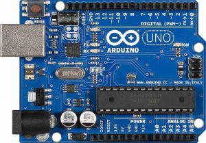
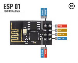
Let’s start by connecting the Arduino UNO to the computer through USB. Connect the esp8266 as follows:
- VCC – – > 3.3V (Arduino UNO)
- GND – – > GND (Arduino UNO)
- CH_PD / EN – – > 3.3V (Arduino UNO)
- RST – – > Normally Open; GND to Reset) (we can use push button)
- GPIO0 – – >Normally Open; connect to GND while programming (Arduino UNO)
- TX – – > TX (Arduino UNO)
- RX – – > RX (Arduino UNO) (don’t forget voltage divider)
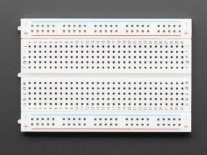
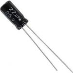
Voltage Divider
Connect the 2.2k/ohm resistor from ground to the ESP RX. Then add a 1k/ohm resistor between the Arduino and the ESP RX.
Note: Test the jumper wires before connecting using a multimeter to confirm they’re not broken.

Testing Esp266 connected correctly.
- Check if the led blinks or if the power led turns on (in Esp82600 ) after connecting to the Arduino.
- It’s fine if the led only blinks once at first. There are varieties of Esp-01 modules in the market. Mine doesn’t have a power lead. Most of the tutorial shows the Esp-01 with two Leds. Check the led on your ESP module. If you have only one led, you won’t see the red power led.
Now, on Arduino IDE go to Tools->Serial Monitor


Make sure you set the first drop down to “Both NL & CR” and boud rate to 115200.
Now, Type AT command. it Should return ok. like this

You can find all the AT commands here. These are serial commands. These commands need to be run through serial communication. Now let’s start deploying webserver code to Esp8266.
Note: Once you deploy blank or any code to Esp8266, it won’t respond to Serial AT commands like in the above image. Because once blank or any code is deployed to the esp8266, it will replace its default firmware code with the deployed one.

As we are deploying through the Arduino Uno. set a Port to the one that say Arduino Uno.

Copy the code below to your Arduino IDE. Update the wifi ssid and password and save it.
#include <ESP8266WiFi.h>
#include <ESP8266WebServer.h>
#include <SoftwareSerial.h>

#include <WiFiClient.h>
const char* ssid = "your_wifi_name";//type your ssid
const char* password = "wifi_password";//type your wifi password

bool lightOn = false;
ESP8266WebServer server(80);
SoftwareSerial s(2,3);
void setup() {
  Serial.begin(115200);
  s.begin(9600);
  delay(10);

  // Connect to WiFi network
  Serial.println();
  Serial.println();
  Serial.print("Connecting to ");
  Serial.println(ssid);

  WiFi.begin(ssid, password);

  while (WiFi.status() != WL_CONNECTED) {
    delay(500);
    Serial.print(".");
  }
  Serial.println("");
  Serial.println("WiFi connected");

  // Start the server
  server.begin();
  Serial.println("Server started");

  // Print the IP address
  Serial.print("Use this URL to connect: ");
  Serial.print("http://");
  Serial.print(WiFi.localIP());
  Serial.println("/");
  restServerRouting();
  // Set not found response
  server.onNotFound(handleNotFound);
  server.begin();

}

void loop() {
  server.handleClient();

}

void getHelloWord() {
    server.send(200, "text/json", "{\"name\": \"Hello world\"}");
}

void restServerRouting() {
    server.on("/", HTTP_GET, []() {
        server.send(200, ("text/html"),
            getHtmlContent());
    });
    server.on("/helloWorld", HTTP_GET, getHelloWord);
    server.on("/LED=ON", HTTP_GET, []() {
        s.write("light_on");
        lightOn = true;
        server.send(200, ("text/html"),
            (getHtmlContent()));
    });
    server.on("/LED=OFF", HTTP_GET, []() {
        s.write("light_off");
        lightOn = false;
        server.send(200, ("text/html"),
            (getHtmlContent()));
    });
}
String getHtmlContent(){
  String lightStatus = "OFF";
  if(lightOn){
    lightStatus = "ON";
  }else{
    lightStatus = "OFF";
  }
  return ""
  "<!DOCTYPE html>"
  "<html>"
  "<head>"
  "  <meta charset=\"utf-8\">"
  "  <meta name=\"viewport\" content=\"width=device-width, initial-scale=1\">"
  "  <title></title>"
  "  <style type=\"text/css\">"
  "    .button{"
  "      display: inline-block;"
  "      border-radius: 25px;"
  "      padding: 20px;"
  "      border: 1px solid;"
  "    }"
  "  </style>"
  "</head>"
  "<body>"
  "<div style=\"text-align: center;\">"
  "  <h1>Esp-01 Web Server</h1><br><br>"
  "  <h2>Light Status: "+ lightStatus +" </h2><br>"
  "  <a href=\"/LED=ON\" class=\"button\">Turn Light On</a> <br><br>"
  "  <a href=\"/LED=OFF\" class=\"button\">Turn Light Off</a><br><br>"
  "  </div>"
  "</body>"
  "</html>";
}
// Manage not found URL
void handleNotFound() {
  String message = "File Not Found\n\n";
  message += "URI: ";
  message += server.uri();
  message += "\nMethod: ";
  message += (server.method() == HTTP_GET) ? "GET" : "POST";
  message += "\nArguments: ";
  message += server.args();
  message += "\n";
  for (uint8_t i = 0; i < server.args(); i++) {
    message += " " + server.argName(i) + ": " + server.arg(i) + "\n";
  }
  server.send(404, "text/plain", message);
}
Connect the esp82666 GPIO0 and Arduino Uno reset pin to ground. then press the reset in Esp82600.
Now upload the code from Arduino Uno.

It should look like this
If you get an error while compiling sketch check your code. If you get an error while uploading then check your wire connection. make sure GPIO0 is connected to ground and you press the Esp8266 reset button after connecting GPIO0 to ground. and also make sure Arduino Uno reset pin is connected to ground.
Now remove the Esp8266 GPIO0 and Arduino reset pin from ground. Disconnect RX/TX pin from Arduino Uno. Then, in Arduino IDE switch Board back to Arduino Uno. Then upload blank sketch.
Connect Esp8266 RX/TX back to Arduino RX/TX. In Arduino IDE run serial monitor. Then, press reset button on Esp8266.
Note: make sure your boud rate is in 115200.
Once you get serial output like in below image, we are ready to deploy code on Arduino.

Copy following code to new sketch
#include <SoftwareSerial.h>
int ledPin = 13;  // LED connected to digital pin 13
String incomingCommand;
SoftwareSerial s(3,4);
void setup() {
  Serial.begin(9600);
  s.begin(9600);
  delay(10);
  pinMode(ledPin, OUTPUT);  // sets the digital pin 13 as output
  Serial.println("Ready");
}

void loop() {
  while (s.available()) {
    delay(3);
    char c = s.read();
    incomingCommand += c;
  }
  incomingCommand.trim();
  if (incomingCommand.length() >0) {
    if (incomingCommand == "light_on"){
      Serial.println("switching on");
      digitalWrite(ledPin, HIGH);
    }
    if (incomingCommand == "light_off")
    {
      Serial.println("switching off");
      digitalWrite(ledPin, LOW);
    }
    Serial.println(incomingCommand);
    incomingCommand="";

  }

}
Disconnect RX/TX pins and upload it.
Now, connect Esp8266 RX/TX back to Arduino RX/TX.

Note: Connecting Arduino reset to ground switch serial monitor to esp8266 (that means it will print Serial.print etc from esp8266). Disconnection Arduino reset pin switch serial monitor back to Arduino.
To check your server Ip address, connect Arduino reset to ground. then go to Tools-> Serial monitor . switch boud rate to 115200 and press reset in esp8266. you will get following output.

Once you see similar to above image. Connect ESP RX to Arduino pin 3 and ESP TX to Arduino pin 4. disconnect Arduino Reset pin from ground.

Now open that ip address in your browser.

Disconnect the Arduino reset pin. Now it’s ready. Lets try Turning light On/Off from browser